My NIS 26 PRESTO was fitted with a kick-up rudder which most times worked very well. However there have been occasions when running in shallow water the rudder strikes bottom and kicks up, which it should do, however when under full sail steering becomes a mammoth task. Instead of a vertical blade a meter or so down you now have a horizontal blade a meter or so out the back. Not good. I once sailed for an hour with a novice on the tiller, he kept quietly saying “gee this is hard work” and me I was just enjoying the day out, until we were about to ram another yacht, “steer away” I quietly commanded in my best squeaky voice “I am trying but it won’t go” only then did I discover the board had kicked up. Poor bloke had been steering all this time with the board out the back, needless to say he hasn’t asked to go out again.
So the time came to change the rudder design and thanks to NIS. Boats Robert Ayliffe a new vertical drop rudder and box arrived and fitted perfectly to the existing pinions.
I had in mind using the existing tiller adapted to the new rudder box unfortunately this was not and option, as the angle from the rudder box up over the motor housing was such that constructing a new tiller was the only was to go. Several constraints had to be considered in the design. One the tiller had to clear the motor housing, and then it had to follow the line of the top of the rudder box before dropping down to a working height for the helmsman. Then to top it off there needed to be room under the tiller to allow the handle to be pushed down to release the rudder from the clamps of the rudder box allowing the rudder to drop.
Taking all these constraints into consideration it became obvious that a curved tiller is the only way to go.
As the tiller starts off at the box end at 85mm across and the connection plates to the rudder box are 40mm deep to steam bend a piece of timber of around 90 mm by 50mm in tight curve didn’t strike me as being easy. So laminating was the only practical solution. What timber to use? Well I have a nice stack of very dry furniture grade New Guinea Rosewood, no question on what to use. Unfortunately New Guinea Rosewood is quite a brittle timber and I have found it tends to snap when bent dry, being well seasoned. The only way to get good curves without damage is to reduce thickness to less than 6mm and in this case down to 5mm. Ok we have the timber, we know what is needed, how do we progress? What follow are the major steps I used to build the new tiller.
- A pattern is made from hardboard using the top edge only for the shape on the boat. Time to get artistic. Mark the angle up from rudder box, mark the height above the engine housing, free hand some curves.
- Final shape fitted and eyeballed for look using the top edge only. Looks like a tiller.
- The pattern is then tacked to a dressed hardwood plank and steel angles bolted to the top edge of the pattern. I used a heavy hardwood plank for stability of the form.
- Over several days the laminates were slowly drawn to the mould without glue. To tease them into their final shape and to evaluate the difficulties and possible failures.
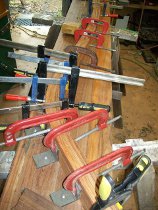
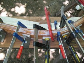
- Time for glue. The dry run established that it’s a big ask to do the full 50mm of lamination in one go. Best to do it in two glue ups. Hint, you need all the clamps you have plus more. This is only half of what ended up on each of the clamp ups. Each laminate was evenly spread with glue using a notched spreader with around 3mm wide notches.
- First lamination released after a few days of epoxy glue drying. I left the lamination clamped up for 5 days to ensure the epoxy was as fully cured and hard, to minimize the spring back. Even so there was around 6mm spring back. I did consider adding extra curve for the second glue up of laminates but as the curve was not that critical left well alone.
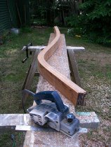
- Once second set of laminates glued in place the glue was left clamped for a further 5 days to maximize the cure. Even so a small amount of spring back was evident. Next step to clean up the edges. Using an electric planer to remove and smooth the edges before feeding through a thicknesser to get an even board thickness.
- Now the nerve racking bit. Cutting to length especially the rudder box end as too much and the curvature and alignment to the rudder box will be out. So small steps, first clamp to out side of rudder box support tiller and step well back, does it look right, have a cuppa, have another look, trim a bit, fit, trim a bit more yes leave at that. As it happened another 12mm came off in the end to allow the tiller to tip right back. See final photos. And the yellow pages are useful, as the supports.
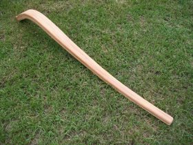
- Ok drama over, rudder box end cut and fitted so now we have a tiller that is 85mm wide from rudder box to steerage. Not a good look, strong, but not comfortable. Again it’s what looks nice to the eye and is comfortable on the hand, drives the shape. At the steerage end I found a diameter of around 40mm comfortable. So a taper from the rudder box end of 85 mm to 40mm at steerage end was decided on. In my case a straight taper rather than more curves. One side was cut, shaped to the lines with hand planes, a pattern developed, working off a center line, then scribe to the opposite side for final shaping
- Now all that’s left is trim the steerage end to length run a router with a nice curvature around the edge, sand and fit.